EspañolEnglishHome Contact Why advertising? Sponsors Subscriptions
Logo Calc-útiles Calc-útiles Pino
Calculation utilities
for Architects
and Engineers.
(c) 2003 - 2024


Home


Calculation utilities

Loads SteelConcreteGeotecnics
(*) Only for users with an active subscription (+info)

General information

Contact


Calc-útiles Pino - (c) 2003 - 2024


Calc-útiles Pino - Structural calculation utilities - Sponsors:
Logo Videomedico Logo Clínica Virgen de Camino Logo Tline Logo Half&Twice

Calculation of the maximum efforts of the reinforced concrete section to bending and axial. Generating of the interaction diagram, both according to the parable-box diagram as the rectangular digram of the concrete, and the strain domains diagram, according to the EHE-08.

Abstract
  • The interaction diagram of the concrete section is developed according to EHE-08, with the behavior of concrete specified in Article 39.5, following both the parable-box diagram as the rectangular stress-strain diagram of the concrete. In this interaction diagram, the combination of the maximum axial and bending moments of the section is obtained from the maximum deformation that admits the section, according to the diagram of deformation domains described in Article 42.

  • The domain deformation diagram is generated from the maximum admissible deformation of concrete and steel, when considering the neutral axis moving from -∞ to +∞.

  • The interaction diagram is obtained by calculating for each position of the neutral axis, the balance of forces and moments about the midpoint of the concrete section.

  • The forces and moments of the reinforcements are calculated by adding each steel bar. The forces and moments of the concrete are calculated based on the compressed concrete area from the parabola-rectangle diagram and the rectangular diagram.

  • The domain deformation diagram is as follows:
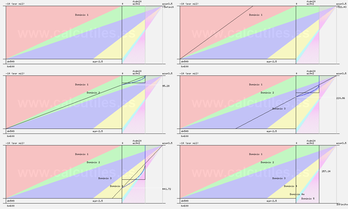
    Strain domains

Calculation
Parameters:    
Materials:      
Concrete: fck =N/mm2    
Concrete deduction factor Yc =  Yc = 1.5 except in accidental situation (Yc = 1.3), fatigue or fire (EHE-08, 15.3)  
Compression fatigue factor αcc =(*1) Usually αcc = 1 (in EHE-98 αcc = 0.85)  
Steel: fyk =N/mm2 Ys = 1.15 except in accidental situation (Ys = 1.0), or intense control (Ys = 1.10) (see EHE-08, 15.3)
Steel deduction factor Ys =  
Steel elasticity modulus Es =N/mm2 Usually Es = 200,000 N/mm2 (EHE-08, Art. 38.8 and comments at Art. 38.4)
Section:   
Width (máx. 2000) =mm 
Section
Height (máx. 2000) =mm 
Top nominal cover =mm 
Bottom and sides nominal cover =mm 
Renforcement:   
Styrrup: ø =mm(*2) 
Top reinforcement:
ø
mm  
Bottom reinforcement:
ø
mm  
Lateral reinforcement (each side):
ø
mm(*3)  
Check point:      
Neutral axis depth:mm (For results in a specific point of the charts)
Draw parable-box diagram:     
Draw rectangular diagram:     
 
(*1)The fatigue factor reflects this effect in concrete, when subjected to high levels of compression due to long-term loading. It is generally adopts αcc = 1, although the author of the project should consider its reduction to 0.85, if the permanent and total loads ratio is high, or depending on the characteristics of the structure (EHE-08, 39.4)
(*2)The regulation allows to reduce the bending radius in hoops or stirrups less or equal to 12 mm diameter, which is recommended not to use larger diameter bars, being preferable to place double or triple styrrups if required. (EHE-08, 69.3.4).
(*3)The side reinforcement introduced is considered in the calculation. If you do not want to consider it resistant for allocating its mechanical capacity to horizontal deflections, or for any other reason, you should not enter it into the program. However, it must be verified that reinforcements separations specified in the regulations are met (it can be used the "Aggregate and rebar gaps" utility)
Unlimited calculations for users with an active subscription. (+info)

Results:   
Materials:     
Elastic steel deformation =2.5  Deformation of steel at yield
Concrete compressive strength fcd =20N/mm2 (EHE-08, 39.4)Concrete compressive strength
Break strain at simple compression εc0 =2 (EHE-08, 39.5)Break strain at simple compression
Ultimate flexural strain εcu =3.5 (EHE-08, 39.5)Ultimate flexural strain
Concrete parable-box diagram:     
Grade of parable n =2  (EHE-08, 39.5)Grade of parable
Highest traction =-699.35kN, con0mkN 
Maximum simple bending moment =Value visible only to users with an active subscription. (+info)
Maximum moment combined with axial =522.95mkN2183.16kN 
Highest compression =5443.4kN, con0mkN 
Rectangular concrete diagram:     
η =1  (EHE-08, 39.5)Eta factor
λ =0.8  (EHE-08, 39.5)Lambda factor
In Checkpoint: η(50) =1  (EHE-08, 39.5)Eta factor
In Checkpoint: λ(50) =0.07  (EHE-08, 39.5)Lambda factor
In Checkpoint: rectangle area(50) =0.8kN/mm (EHE-08, 39.5)A = [λ(50) * h] * [η(50) * fcd]
In Checkpoint: Force(50) =320kN (EHE-08, 39.5)F = A * b
In Checkpoint: Bending moment(50) =89.6mkN   
Highest traction =-699.35kN, con0mkN 
Maximum simple bending moment =Value visible only to users with an active subscription. (+info)
Maximum moment combined with axial =530.46mkN2157.47kN 
Highest compression =5443.39kN, con0mkN 
Interaction diagram:     
Interaction diagram


Author's notes
  • These calculations proposed by the regulation are very accurate and instructive, but in the author's opinion, its accuracy is dissolved in practice when sizing elements with load increment factors of a magnitude order as high as the current 1.35 and 1.5.

  • In concrete sections with unsymmetrical reinforcements or covers, the balance in pure traction or compression at both extremes is not reached, appearing moments in axial extreme values​​.

  • Although at the EHE 08 the fatigue factor has increased by around 17% compared to the EHE 98 (from 0.85 to 1), the maximum resistant efforts of the section are not increased this percentage, but at much lower percentages. In fact it has been observed that in some cases the maximum tension stress and the maximum bending moment are reduced. With this it seems that to make the calculations with the fatigue factor as EHE-98 is not in all cases on the safety side.

Version 15/11/2012


Calc-útiles Pino users comments. To leave a comment about this page press  
Logo Calc-útiles Calc-útiles Pino

Structural calculation Forum


Pino wrote
  • Puedes escribir aquí tus comentarios.

    Saludos.
Pino wrote
  • Me surge una duda de interpretación de la norma:

    Según la EHE-08, el canto útil es "la distancia entre el centro de gravedad de la armadura en tracción o menos comprimida y la fibra más comprimida de la sección" (EHE-08, 42.1.3 comentario).

    Lo que no define es qué se entiende por "Armadura en tracción". ¿Se refere a la barra de acero más traccionada? ¿O a un grupo de barras? es decir:

    1- Si el armado traccionado consta de barras del 12 y del 20, ¿Debemos considerar el centro de gravedad de todas las barras o sólo de las del 12 (cuyo centro de gravedad está más alejado de a fibra superior)?

    2- Si el armado traccionado son barras agrupadas, ¿Debemos consderar el centro de gravedad de los grupos?

    3- Si el armado traccionado está en dos o más capas ¿Debemos reducir el canto útil hasta el centro de gravedad de todas las capas, o consideramos hasta la capa inferior que estará más traccionada?

    4- Si hay armadura de piel que está traccionada, ¿Debemos reducir el canto útil hasta el centro de gravedad de todas las barras traccionadas?

    5- Si la sección está en compresión compuesta, ¿Debemos considerar el canto útil desde la fira superior hasta el centro de gravedad de todas las armaduras puesto que todas están comprimidas, o sólo hasta la barra menos comprimida?

    6- Si en tracción tenemos redondos del 10 y del 32, la cara del redondo más alejada de la fibra comprimida es la del 32 pero el centro de gravedad más alejado es el del 10, ¿Hasta dónde se mide el canto útil?

    Si alguien puede aclarar el tema, le estaré muy agradecido.
Luis González wrote
  • El canto útil debería, en mi opinión, calcularse desde la fibra más comprimida hasta el baricentro del redondo traccionado más alejado. Por ejemplo, si pensamos en un pilar cuadrado con la fibra neutra paralelo a una de sus diagonales, el canto útil será la distancia entre una esquina del pilar y el centro del redondo situado en la esquina opuesta
Juan Sanchez wrote
  • Posiblemente, dado el tiempo transcurrido, tienes resuelta la duda. yo considero que es la distancia desde el centro de gravedad de la armadura más traccionada o más separada de la fibra mas comprimida y por eso en los comentarios te remite a 37.2.4. donde el recubrimiento es a la cara de la armadura.
Luis wrote
  • Creo que el diagrama de interacción N-Mf está errado en lo referente al acero. Al verificar la tracción máxima(solo trabajando el acero) creo que hay un factor 10 de mas.
    En mi cálculo en particular, para 4ø25 P.S. y 4ø25 P.I. la página me indica maxima tracción de -1707.39 kN.

    Mi cálculo es:

    A_acero=393mm^2
    Fyd=434.7 N/mm^2
    N=A_acero*Fyd= 170.8 kN

    Un saludo, espero respuesta.
    Gracias por la página.
Luis wrote
  • Me desdigo de mi ultimo comentario, fallo mio.
    Un saludo
Calc-útiles Pino users comments. To leave a comment about this page press

.